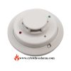


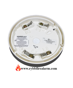
System Sensor B501-WHITE Detector Base
$21.00
50 in stock
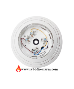
System Sensor B501-WHITE
A plug-in detector base intended for use in an intelligent system with screw terminals provided for power (+) and (–). And remote annunciator connections. Communication takes place over the power (+) and (–) lines in the System Sensor Detector Base.
For signal wiring (the wiring b etween interconnected detectors and modules). It i s recommended that the wiring b e no smaller th an 18 AWG (0.823 square mm). Wire sizes up to 12 AWG (3.31 square mm) may b e used with the base.
Alarm system control panels have specifications for allowable loop resistance.
Consult the control panel specifications for the total loop resistance allowed b efore wiring the detector loops.
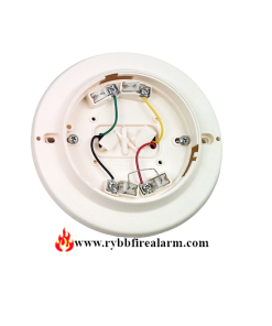
Make wiring connections by stripping about 3⁄8 inch (10 mm) of insulation. From the wire end (use strip gauge molded-in base). Th en slide the wire under the clamping plate and tighten the clamping plate screw. Do not loop the wire under the clamping plate.
Check the zone wiring of all bases in the system b efore installing the detectors. This includes checking the wiring for continuity, correct polarity, ground fault testing, and performing a dielectric test.
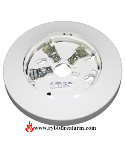
The base includes an area for recording the zone, address. And type of detector to b e installed at that location. This information is useful for setting the detector head address. And for verification of the detector type required for that location.
On ce all detector bases have b een wired and mounted. And the loop wiring has b een checked, the detector heads may b e installed in the bases.
| Weight | 1 lbs |
|---|---|
| Dimensions | 6 × 6 × 6 in |
Be the first to review “System Sensor B501-WHITE Detector Base”
You must be logged in to post a review.
Related products
System Sensor
Edwards EST
Vigilant
Gamewell FCI
System Sensor
Edwards EST
Reviews
There are no reviews yet.