
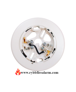
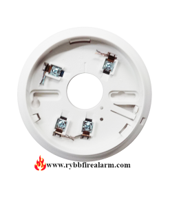
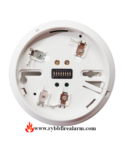
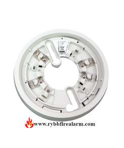
Siemens DB-X11RS Detector Base W/Relay P/N: 500-096125
$50.00
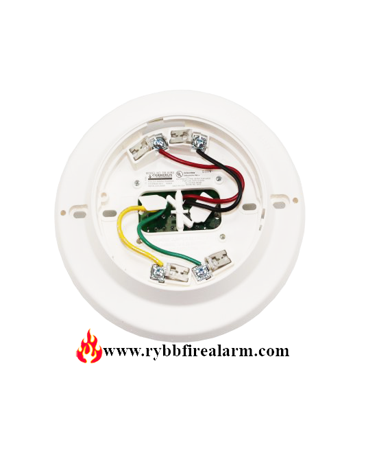
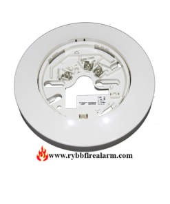
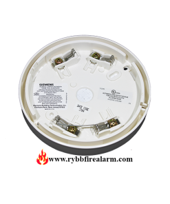
Siemens DB-X11RS is provided with a separate base that attaches to a standard 4-inch square or a 4-inch octagonal electrical box.
4 in stock
Siemens DB-X11RS Detector Base W/Relay P/N: 500-096125
Detector and base locations shall follow the drawings provided or approved by Siemens Industry, Inc. or its authorized distributors. This is extremely important! The detector placements shown on these drawings were chosen after a careful evaluation of all facets of the protected area. When drawings are not available, refer to Detector Placement section of detector Installation/Wiring Instructions and to NFPA 72, National Fire Alarm Code, Chapter 5 and CAN/ULC-S524.
Detectors should be interconnected as shown in Figure 1 and wired to the control panel following the wiring connection drawing installed on the inside face of each control panel cover. Duplicate wiring information is also in the Installation, Operation, and Maintenance Manual provided with every control panel. Also, note any limitations on the number of detectors and restrictions on the use of remote devices permitted for each circuit.
Siemens DB-X11RS is provided with a separate base which attaches to a standard 4 inch square or a 4 inch octagonal electrical box, with the box size as well as depth required by the NEC for the number and size of conductors used. Wire size: max – 14 AWG, min – 18 AWG.
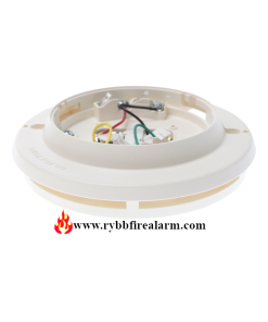
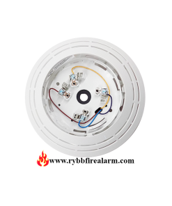
Installation
- Route all wires outward from outlet box
- When the ALARM LED viewing is critical, position the LED mark in the base in the intended direction
- Route wires through the hole in the center of the base and mount base to outlet box. Besides, make connections directly to the base terminals.
- To insure proper installation of the detector head into the base:
- Route wires away from connector terminals.
- Take up all slack in the outlet box
- Properly dress and position all wires flat against the base
- Check that screw terminals are tight
| Weight | 1 lbs |
|---|---|
| Dimensions | 7 × 6 × 1.5 in |
Be the first to review “Siemens DB-X11RS Detector Base W/Relay P/N: 500-096125”
You must be logged in to post a review.
Related products
System Sensor
Vigilant
Detector Bases
Edwards EST
Edwards EST
Reviews
There are no reviews yet.