
EDWARDS EST 4-PPS/M Primary Power Supply w/ Module (New)
$996.60
Edwards EST 4-PPS/M Primary power supply
11 in stock
Edwards EST 4-PPS/M
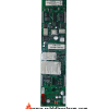
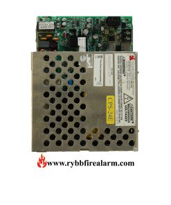
System power supplies consist of two assemblies, a high-efficiency switch mode power supply card, and a power supply monitor module. The monitor module mounts to the local rail and distributes the power from its supply to the local rail. The local rail distributes power from all power supplies to other local rail modules. And user interface cards resulting in “Shared Power” throughout the system. The 4-PPS/M can b e configured as a primary power supply (PPS), booster power supply (BPS), or booster charger (BBC).
A 4-PPS/M configured as the PPS provides filtered, regulated power to the rail chassis modules. And 24 VDC for operating ancillary equipment. The PPS consists of a power supply unit (PSU) mainboard and a monitor (MON) module.
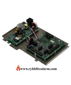
Each booster power supply consists of the PSU mainboard and MON module. The booster power supply MON module provides the interface between the booster and the panel. Making the required data and power connections to and from the rail chassis.
Maximum use of available power is achieved by configuring the power supplies in parallel. This results in a potential reduction in the number of power supplies necessary to meet requirements.
As many as four power supplies combined in a single enclosure provide up to 28 amps of available power. Battery backup is provided using one to four sets of batteries, depending on standby power requirements.
System power supplies mount to the back of the chassis units or wall boxes. Access to auxiliary power is via easily accessible terminal blocks located on the power supply monitor module. Each power supply produces 7 Amps of filtered and regulated power.
| Weight | 5 lbs |
|---|---|
| Dimensions | 17 × 14 × 10 in |
Related products

Internal Power Supplies
Internal Power Supplies

Internal Power Supplies

Internal Power Supplies


Edwards EST

Internal Power Supplies